The PROBAnD Railway Crossing Specification
Contribution to the SDL-2000 Design Contest of the 3rd SAM Workshop
Stefan Queins, Andreas Metzger
The railway
crossing design contest has been approached with an extension of our
requirements engineering method PROBAnD (Prototyping-, Reuse-,
and Object-based Building Automation Development),
which has originally been developed for specifying complex building automation
systems software. This method is presented in detail in our research paper
contribution to the SAM
2002 workshop called "Early Prototyping of Reactive Systems Through
the Generation of SDL Specifications from Semi-formal Development Documents".
To better understand our design contest results
(especially the final SDL specification), which
have been attained with an extension and modification of the PROBAnD method,
an informal description of the method's development activities and documents
will be given in this document.
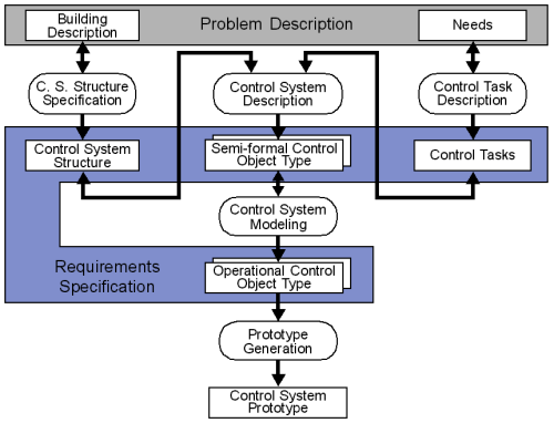
Fig. 1: Overview of the PROBAnD Requirements Engineering Method
As an input, the requirements engineering method PROBAnD takes the problem
description, which is divided into the building description
and a collection of needs (c. f. Figure 1).
The building description contains a description
of the buildings structure. Further, the buildings installation is depicted.
From this building description, an initial control system
structure can easily be derived because the control objects are
most often identical to the the buildings objects or are a sub-set of
these. To handle the huge number of control objects, control object
types are formed, which are aggregated according to the hierarchy of
the buildings objects. As requirements engineering proceeds, this control
system structure can be refined, as long as the strict aggregation hierarchy
of control object types is maintained.
The other part of the problem description is made up by a collection
of needs. These needs informally describe the
control system from the point of view of the users. The needs are split
into less complex control tasks such that they
can be assigned to single control object types.
As a guideline for the above steps, we suggest that the responsibilities
of a control object type at a certain level should match the control
tasks that can be performed at that level, which allows minimizing
the flow of information. This distribution of responsibilities, which can
easily be applied in the domain of building automation systems, has similarities
to an organizational hierarchy. Communication between control objects
is realized through the exchange of signals (which may have parameters)
that are only allowed to travel along the aggregation hierarchy. This helps
maintaining the easy comprehensibility of the specification, and allows
the creation of documents from a set of few templates to simplify recurring
activities (like specifying communication channels between control object
types).
After the control object types have been identified and control
tasks have been assigned, strategies for realizing the control
tasks are informally given in natural language, leading to a collection
of semi-formal control object types, which
are expressed in HTML documents.
From these semi-formal control object types, operational
control object types are specified in SDL documents, which together
form an executable SDL specification.
The executable specifications are used for creating control
system prototypes, with which the test of the
systems becomes feasible. To ease the interaction with the system during
run-time, Java panels (GUIs) can be used that allow
the dynamic change of parameters and settings.
One important aspect of our process is that the development time for
creating and modifying each document is recorded (for each document a "Version
History" is kept), which allows measuring the overall development
effort.
Design Contest Results:
-
Problem
Description (Version
History): The description of the entities of the railway crossing (which
take the part of the "building description"), and the collection
of needs, are contained in a single document, the original statement
of requirements of the SAM design contest. The initial
problem description has been extended to show how the specification
could be addapted to these new requirements. These changes are reflected
in the Version Histories of the respective documents by the version comment
'CHANGE of requirements regarded' or a similar text. The effort for these
modifications is listed below.
-
Control
System Structure (UML-Diagram,
Version
History): According to the approach for the building automation domain,
the system structure has been attained very early in development by using
the entities of the physical system as a starting point; e.g. the trains,
the gate or the sensors. As the whole railway crossing system had to be
specified, the controller part and the actual environment had to be considered.
Thus, each entity is represented from the point of view of the controller
(XxxCtrl) and from the point of view of the environment (EnvXxx).
Note, that each sensor and actuator on the Env-side of the system
communicates with the respective entity on the Ctrl-side of the
system. As an extension to the PROBAnD approach, some entities in the control
system (e.g. trains) are instantiated during run-time, i.e. after the system
has been initialized. This is specified by a variable multiplicity of
n
in the documents.
-
Control Tasks: The control tasks have been directly
specified in the semi-formal control object type documents
because their assignment to control object types has already been known
when the tasks were specified.
-
Semi-Formal Control Object
Types:
-
Operational Control Object
Types: As an extension to the PROBAnD method, the instantiation
of control object types during run-time is realized by dynamically creating
SDL processes.
-
SDL
Specification (Version
History, Telelogic
Tau Organizer File for WIN32): The specification has been used to generate
protoypes
of the railway crossing system with Telelogic Tau. In order for the system
to start up correctly, a file named sockadr
needs to be created in the current directory. This file has to contain
four lines, stating the correct hostname and port for the panel, the last
two lines can be set to an arbitrary value.
For initializing the system (number of tracks, settings of distances,
...) a Java panel can be used. However, if the Java
platform is not available (or difficulties in connecting the panel to the
prototype persist) the simulator interface can be used to start a demo.
Proceed as follows:
-
start (realtime) simulation, then enter:
-
set-trace 1
-
go
-
wait, until no more output is visible on stdout, then stop simulation (break),
and enter:
-
Output-To physValIn ('obj1', 'demo') ProtoCtrl
-
Test Cases: For Testing the
system behavior, each active entity of the model (trains, signals and the
gate) creates a logfile in the logs-directory (for an example see here).
Each of these files is named after the actual instance name of the object
concatenated with 'Log' and contains information like the position of a
train, the state of a signal, etc. These files have been used to create
graphical outputs for each test-case, which show the behavior of the system
in an easily comprehensible form (for an example see here).
-
Java Panel:
The panel can be used for dynamically interacting with the railway crossing
system. After the prototype has been started, the panel can be connected
to the hostname and port specified in the sockadr-file (see above) as follows:
-
change to the Java-Directory,
where the Java-Files are located, enter:
-
java main.RWPanel obj1 <hostname> <port>
-
Effort: The effort of each development activity is recorded
in the Version Histories of each document and also in the overall Process
Trace. The following table shows the effort distribution (according
to the activities introduced above). The total effort for the specification
of the railway crossing was 4134 min (68.9 hrs).
| Activity |
Affected Part of System |
Initial Effort [min] |
Effort for Modification [min] |
| Constrol System Structure Specification |
|
54 |
0 |
Control Task Description +
Control System Description |
Env-side |
493 |
2 |
| Ctrl-side |
161 |
16 |
| Panel, Top-level Object Type |
106 |
0 |
| Control System Modeling |
Env-side |
1032 |
4 |
| Ctrl-side |
197 |
54 |
| Panel, Top-level Object Type, Signal Definitions, Tests |
2012 |
3 |
| TOTAL |
|
4055 = 67.6 hrs |
79 = 1.3 hrs |