MSC-92 Tutorial
Introduction
Here we give the background for the use of message sequence charts, its history and its early uses. For a quick summary of MSC and a good starting point for linking to all aspects of MSC look up "Summary of tutorial" .
The diagrams of this tutorial contain hidden menues. By pressing the mouse button at various places in the diagrams, context specific menues will appear. They will normally give you the choice to open up the definition of the concept, or to go to somewhere in the book where you can get more information on this concept or how it is used in the example.
To see whether you are in a menu-sensitive area, watch the cursor change appearance.
What is a message sequence chart?
Our domain is systems with a number of independent actors which interact through sending messages to each other. The behavior of the actors are dependent upon the messages they receive. In this context there are two orthogonal perspectives:
- Emphasize the behavior of each individual actor, and try to describe the behavior as completely as possible;
- Emphasize the interaction between the actors indicating that the interplay between the actors is the most important aspect. Often only a small portion of the total variety of behavior is described.
The first approach is the perspective of SDL, while the second approach is the view of MSC. While SDL describes the painting of a picture, MSC describes the picture. MSC thus describes the product while SDL describes how the product is reached - the process. The skills needed to describe the process (how to paint) are not equivalent to the skills needed to describe accurately the product (the painting). Just as a theater critic may not necessarily be the best playwright (or vice versa), the customer may very well be a good MSC user while the engineers take care of the SDL design.
MSC concentrates on describing the message-sending between instances . The important invariant for messages is that a message must be sent before it is received.
Figure 1: An MSC
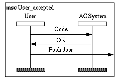
The Figure 1 shows an msc which describes a very simple interaction between a user and an access control system. The user presents (in some way) his personal code to the system which then returns that the user is eligible to enter the door. The user then pushes the door open. This access control example will be used extensively throughout this tutorial. The reader can find more about the example in [25] .
This msc is of course only one situation, and from this msc one cannot deduce others. On the other hand MSC can be understood by almost anyone. Even the market department seems to be able to understand mscs.
The connection between MSC and V&V
In this report we shall look at how MSC can be used in order to improve the formalization of the descriptions. Traditionally MSC (or notations similar to MSC) has been used to sketch interaction sequences in the early phases of the development. In less degree the mscs have later been used as references for more stringent scrutiny of the design or implementation. This is, however, the aspect which we will address in this report.
We will also give a very brief tutorial on MSC to update reader unacquainted with MSC.
Through the standardization of MSC in ITU, the language has evolved from being a simple notation to being a formal description technique. It is theoretically possible and practically feasible to check the consistency between an msc and an SDL description. In that way the correctness and validity of the design can be ascertained.
We will also argue that using MSC in a formal way will decrease ambiguity and improve the overall understanding of the problem domain. Other SISU reports also cover MSC, see [81] , [86] and [166] .
Early uses of MSC
Notations similar to MSC have been used by Norwegian companies for a number of years. NFT-Ericsson, Garex, Stentofon and Telox have all used signal sequence diagrams to facilitate understanding, for intra team communication and for communication with peripheral participants and customers. These companies are now beginning to used case tools which include modules with MSC.
The early uses were mostly to sketch interesting situations in an informal way. The diagrams were decorated freely with proprietary annotations which added to the basic MSC notation. Such annotations included referencing other mscs, alternatives within one msc and looping [86] . We find mscs which are used as high level documentation and msc which give a detailed account of some intricate feature. The different levels of abstraction cannot easily be compared without thorough insight into the problem domain and the system in question.
Standardization of MSC
Several companies have used different dialects of message sequence charts for a number of years. In the SDL user guidelines of 1988 [35] we can find a short section on such sequence charts. At SDL Forum in Lisbon in 1989 a paper on "Extended Sequence Charts" [69] was presented; it marked the start of an effort to define and standardize the MSC language.
The standardization work was carried out by the CCITT Study Group 10 in question 8 on maintenance of SDL, and it led to the acceptance of the language MSC as a recommendation [103] . There was agreement on a language which represents the most basic concepts used within sequence charts. It was acknowledged that there may be a need for developing the language further. For a detailed account of the history of MSC, see [68] .
In the current standardization work, MSC is handled by a separate question in ITU Study Group 10 (question 9). The work is organized in three parts. The overall responsibility of MSC including extensions and modifications is given to Ekkart Rudolph of Siemens, Germany, as the rapporteur of question 9. Furthermore the formal semantics for MSC has been brought forth by the associate rapporteur on semantics, Sjouke Mauw, Eindhoven University of Technology in the Netherlands.
It was recognized already in the former study period that a number of users wanted some concepts to structure their mscs better. Macro concepts and type concepts were suggested in contributions, but the study group decided that the matter should be deferred into the next study period. In this period Øystein Haugen was appointed associated rapporteur of structural concepts.
Instances and Events
In order to be sure that the reader can follow the more constructive parts of this methodology, we shall give a brief introduction to the language MSC 92 as it is standardized by ITU [103] .
The reader should bear in mind the purpose of MSC: to describe the interaction between a set of communicating actors. The focus is on the communication itself, the sequence in which the messages occur and not the reasons for why the messages are sent or what will happen when they are received.
MSC can describe interaction within an SDL system, but MSC as a language is independent from SDL.
The actors of an msc are called instances . They are described by an instance head and an instance end connected by a timeline as shown in
Figure 2: Instance
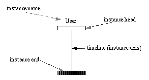
The instance head and instance end represent the start and end of events on the instance timeline within the msc. They do not indicate anything about creation and termination as we shall see below. The timeline of an instance contains a sequence of events . The most basic events are output and input of a message . Each message has exactly one output event and one input event. Messages are communicated between instances or between an instance and the environment . The environment is represented by the frame around the MSC diagram
Figure 3: MSCdiagram
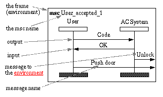
The events are ordered along each timeline , but events on different timelines are not ordered. This means that MSC cannot describe absolute time. In Figure 3 we can deduce that along the User timeline the order is: output of Code , input of OK , output of Push door . From the figure we cannot deduce anything about the order of output of Unlock and output of Push door . In fact this is what the reader may have experienced with such a system. He tries to enter the door after having seen the OK signal from the display (a green light or similar), but pushing the door does not ensure the door to open because the door has not quite been unlocked by the system. Gaining experience he will know how long to wait for the door to open. How long he will have to wait cannot be described in MSC. The distances between the events on the timeline have no significance.
Note also that MSC describes the possible sequences of events, but says nothing about the underlying causes of the events. That the output of Code precedes input of OK does not mean that the output of Code causes input of OK . If we know we are describing behavior of SDL systems, we may deduce that the consumption of Code triggered the sending of OK , but MSC only describes that there is a sequence. MSC does not indicate that there are no other possibilities. Possibly there is another msc in the same MSC document which describes that the message NOK follows the message Code .
MSC describe communication between instances. An instance need not be a process in SDL terms. In Figure 3 we see that AC System is an SDL system.
MSC describes asynchronous communication. Input is normally interpreted as consumption of the message. When messages are asynchronous, it is important to be able to describe message overtaking i.e. that one message may be consumed before another event though the latter was output before the first one. Figure 4 shows an example.
Figure 4: Message overtaking

Timers
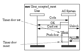
We mentioned in "Instances and Events" that MSC does not express duration as distance on the timeline. As SDL MSC express time only through timers . A timer is a message which is dependent upon time. A timer can be set (started) and reset (terminated) by the instance and a timer may expire which means an input event. Reset timers will not expire
Figure 5: Timer set and timeout

In Figure 5 we describe the situation where the User is accepted, but he forgets to push the door. Possibly he is distracted or he does not see the OK message. The AC System will detect this through the expiration of the timer door . Then it will lock the door such that no unauthorized persons will enter. The preferred situation, however, is the following
Figure 6: Timer set and reset
The User actually pushes the door in Figure 6 and the door opens, which results in a message Opened to the AC System . This again makes he AC System reset the timer door .
The syntax for timers shown here deviates from the Z.120 standard of 1992, but is according to what will become the next standard (Rudolph 1994). The timer set construct and the reset (or timeout) constructs may also be separated. This is practical when the distance between the setting
and fulfillment is considerable like across page boundaries. The timer name must be repeated at the fulfillment. When the timer timeout is separated from the set construct, the hourglass must be repeated. In general the hourglass with corresponding timer name may be repeated any number of times along the vertical line if that is used.
MSC document and Conditions
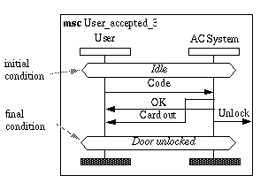
We have in the preceding sections given a number of different MSC diagrams. Some of them are only extensions of some of the others, but some also describe alternatives. When we are faced with a complex reality we must expect to use more than one msc to describe our system. The set of mscs that we use to describe a specific piece of reality is called an MSC document . The question now is how we may describe relations between different mscs within the MSC document. Z.120 includes a mechanism which is called condition which is motivated by the need to combine mscs into larger mscs. The term "condition" is inspired by the Hoare logic (Hoare 1969), but there is no predicate logic behind the MSC term. The MSC condition is merely a label. The idea is that an MSC may have a start condition and an end condition. Combining two mscs where the end condition of the first is equal to the start condition of the second is legal. Combining mscs with unequal conditions is not legal. Conditions may be shared by all instances of an msc or by only a subset of the instances. The concept will become clearer when we look at a small example ( Figure 7 ) which builds upon the mscs that we have already presented
Figure 7: Conditions
We notice that the conditions also have the flavor of states. If an SDL system is described by the MSC document it is feasible to let the conditions represent specific system states. Normally the complete set of system states is too large to describe explicitly as conditions
Figure 8: Alternatives by conditions

The two mscs Unlocked_reset and Unlocked_timeout in Figure "Alternatives by conditions" represent alternative courses of action from the state Door Unlocked . We also notice that they both end in Idle which is also the start condition of User_accepted_3 . This may be interpreted as describing an iterative situation.
Still one should bear in mind that the conditions are not synchronization primitives meaning that the different instances are not "within the condition" all at the same instant. The conditions are merely there for the combination of mscs.
The reader should likewise be aware that the interpretation of conditions in MSC documents is not trivial. The Question 9 group in Study group 10 of ITU have spent some time discussing the issue. Do the presence of conditions mean that the legal combinations of the mscs are implicitly performed? What is then the role of the mscs without conditions?
Coregion and submessage charts
MSC 92 have some more features which in some ways increase the expression power of the language, but which also decrease the simplicity of human understanding and formal interpretation.
Coregion is a concept which is motivated by the fact that sometimes one does not care in which order a set of events occur
Figure 9: Coregion
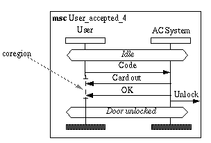
In Figure 9 the User does not care whether he receives/consumes Card out or OK first.
The problem arises if we want to express the following extended situations. The User does not care about OK at all, but whenever he receives Card out he will Push door . Even if we assume only the three messages mentioned, it is not trivial to describe using coregions . We cannot let the coregion comprise the output of Push door , since then there is the sequence where Push door precedes the reception of the two other messages. We could let the coregion comprise only the inputs of messages OK and Card out , and then let the output of Push door follow outside the coregion. This is not quite right either since then the sequence <input Card out , output Push door , input OK > is not described, but it is within our informal statement. The fact is that coregion is not general enough. This means that there is a chance that the MSC describer will describe something which does not quite cover what he wants. And finally the greatest risk is that he believes he has covered it, but formally he has not.
Submsc is motivated by the need to look into an instance for more communication details. Our AC System instance obviously contains a number of "smaller" instances. The requirement analysis may want to express details about the internal behavior of the system
Figure 10: Decomposed
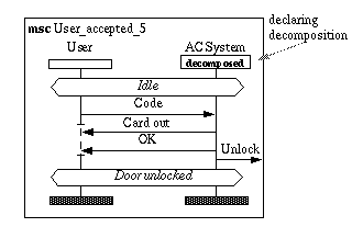
When we want to define a submsc of an instance we depict that in the instance header. The decomposed instance must have the same interface as given by the instance in the msc of higher granularity. With AC System of Figure 10 we must have that input of Code is followed in sequence by the outputs of Card out , Ok and Unlock
Figure 11: Submsc

Figure 11 illustrates two problem areas of the submsc concept. Firstly the static requirement that the interface should be exactly matching is not simple to cope with. While one instance' timeline is strictly ordered, it is seldom the case with the external events of an msc with independent instances. In our example the message Synch has been added for the sole purpose of forcing the output of OK from Panel to environment to precede output of Unlock to the environment. Synch is then only a pseudo-message only present for synchronization, a synchronization not actually wanted in reality. In this case we could have loosened up the msc User_accepted_5 by containing the three outputs in a coregion of instance AC System .
Secondly there cannot be more than one submsc with the same name. This makes it impossible to decompose instances with the same name from different upper level mscs. This problem has been dealt with in MSC-96.
Instance creation and instance stop
Almost by definition since MSC is the description of the "picture", it is hard to imagine how we should describe an arbitrary number of instances. On the other hand that is what dynamic creation is all about, to create a number of instances depending on the situation. We shall not dwell in this philosophical corner, but show how creation and termination of instances are described in MSC (see Figure 12 )
Figure 12: Instance dynamics
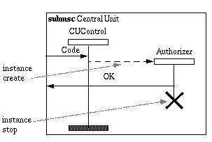
The idea here (though rather far fetched) is that the CUControl needs to create a new process in the big mainframe computer to perform the task of authorizing the received Code . We see a situation where several Authorizers work in parallel. This would make the Access Control System take more resources from the mainframe computer when there is a heavy load on the access control (like in the morning or the afternoon).
Formal definition of MSC
We present the ideas behind the formal definition of MSC in order to give the advanced reader more background on the semantics of MSC.
Any notation which is driven by user needs is judged by its illustrative properties. This means that the semantics of the charts are often left to the experience and imagination of the readers. Still the use of the notation may serve its purpose well, and actually contribute to the improvement of the description and the understanding. In general informal semantics lends itself to ambiguities, and it was early recognized a need for a formal definition of MSC. Two conceptually different approaches were investigated, one using Petri-Nets [73] and one using process algebra [134] . After considerable discussion and investigation and due to the resources available, a process algebra approach was decided. The formal semantics is found in annexes of the standard Z.120 [105] .
The formal semantics consists of a set of equations which are associated with the constructs of the language. Most of the equations can be seen as transformation rules which transforms one term into another. The whole equational system of MSC can be made into a rewrite system as indicated in [135] . This means basically that any chart in MSC can be transformed into a canonical representation. The canonical representation is a tree where each leaf node is an atomic action and each subtree root a basic operator. The basic operators are the strict ordering operator 1 and the non-deterministic alternative operator 2 . The transformation of the msc into the canonical representation can be done automatically. Two mscs are equivalent if they can be transformed to the same canonical representation.
The formal semantics of [105] takes as basic notion that along each instance axis, the atomic actions are strictly ordered. Atomic actions include output events and input events plus events for timers, internal actions, creation and stop of instances. For simplicity in this paper we consider only output and input events. The events of different instances are in principle not ordered and parallel composition operator can be used on the set of instances. This does not entirely suffice because there is an important invariant in MSC that output of a message must occur before the corresponding input. The formal semantics applies a variant of a "state operator" to filter away those sequences which violates this restriction. For definition of the state operator, see [134] .
We shall give a very small example ( Figure 13 ) which still is complicated enough to illustrate that interleaving of events quickly turn into a number of possibilities
Figure 13: An example for formal semantics

The semantic expression becomes 3 :
Summary of tutorial
MSC is a simple language. MSC is based on intuitive concepts: instances communicating with messages which are described by arrows.
The intuitive nature of MSC is also its disadvantage as the user and reader may jump to semantic conclusions which are not valid. The following properties are important:
- A message is asynchronous, the output must come before the corresponding input .
- The events on an instance' timeline are strictly ordered (if it contains no coregion ).
- The distance between events is not significant.
An MSC document consists of a set of mscs. Different msc within the same MSC document are related by conditions . A condition is a label which signifies a global or local state. Conditions can be used to mark situations where there are different alternative continuations, and they may describe looping.
Structuring concepts are few. An instance (within an msc) may be detailed in a submsc .
A coregion is a part of a timeline which has the property that the events may come in any order. The user should be aware of the power of this construct as it is not always trivial to interpret intuitively.
"Instance creation and instance stop" can also be described.
How to use MSC-92 effectively
Even though MSC is simple and may be read and produced by engineers without much formal training, it is possible to make bad MSC documents. It is possible to make beautiful mscs which say nothing, and it is possible to make messy mscs which are meant to convey critical information. It is possible to make terrible mscs in an early phase which makes it impossible to design a sensible system in a later phase without altering the original mscs considerably. As MSC is used extensively in very early stages of a project, it is utterly important that the mscs are as good as possible. Any early deficiency is punished by multiple troubles later.
In this chapter we shall give some guidelines on how MSC should be used in order to express the real desires. Furthermore we shall give indications about how mscs should be in order to be used in formal contexts for model checking and test generation.
We will use the Access Control System as our example. Due to the very limited space we cannot present more than a moderate extract of the MSC document in this chapter. For the same reason we will refer back to diagrams shown earlier in the report as much as possible.
MSC classification concepts
Validation predicates
Validation is the association of the description with the world. Literally it means to "give value to" the description or system.
We may classify behavior which are expressed by MSC by the validation predicates as can be seen in Figure 14
Figure 14: Venn diagram of validation predicates:
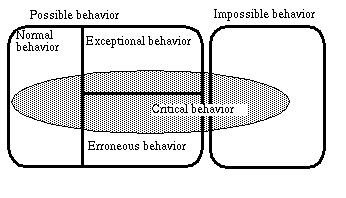
Normal behavior is the behavior which we expect. Very often the normal behavior is the reason for making this system (or module). Exceptional cases are those which may happen, and which we should prepare for, but which we do not consider normal. The erroneous behavior is behavior which we try to avoid, but which should not destroy our system. Recovery should be performed gracefully. Impossible behavior is behavior that cannot happen. The specifier will make certain that the impossible behavior cannot happen through formal reasoning and extensive testing. Critical behavior overlap the other predicates. Critical normal behavior is typically behavior on which the success of the system relies. Auxiliary requirements such as capacity demands are often attached to the critical normal requirements. Critical erroneous behavior is behavior which should be taken care of as smoothly as possible, but the user will normally accept to notice the recovery. Critical impossible behavior is closely related to the overall safety requirements of the system. Some systems may overlook cases considered impossible. If they still prove to exist, a system breakdown is not considered fatal. Other systems will specify recovery even for impossible cases.
Descriptive goal
The descriptive goal of an msc differs depending on when in the system development process, for what purpose and to whom it was made.
Many mscs are used as intermediate sketches which only purpose is to increase the understanding of the participants of some discussion. They are seldom meant to be maintained, but become historical in the sense that they only exist in the record files of the project. The life span of such mscs are very limited but their audiences may be fairly large as they are often on a fairly high abstraction level. We call these mscs historical .
Other mscs are included in top level documentation and may sometimes be included in contracts. They are typically maintained by the documentation system and have no formal connection to the mscs of the dedicated case tool. Their instances and messages are very high level. The system to be made is often seen as one instance. The message names are non-technical. Such mscs are often partial. Their audience is high managers and non-technical decision-makers. We call these mscs documentary .
Then we have the requirements specification. The target audience is project team members and representatives of the customer (or market department). These mscs should be maintained throughout the product life span within the dedicated case tool. The set of requirements form one MSC Document on its own. It will be reviewed during system acceptance.
Integrated case tools like Geode and SDT will encourage the designer to use MSC together with SDL. Block behavior may first be described by an MSC before the complete specification is done in SDL. Consistency can be checked continuously. We call such mscs design mscs. The target audience is the project team.
Finally we have the test mscs. While the requirement mscs may constitute a subset of the test mscs, the requirement mscs will normally not suffice since information and creativity have been added in design and implementation phases. The test mscs are detailed descriptions of behavior which are important for the correct behavior of the system. The target audience is the testers and the managers. The life span is long since the test suite should be repeated automatically after each modification during maintenance.
Step 0: Make explicit the company MSC strategy
MSC is used in several ways in the system development process. The role of MSC is different in the different situations. It is important that the company (or project) has a clear notion of how they try to use MSC. In this section we shall develop a check list of questions which should increase the awareness of the MSC strategy in the company.
What tools will be used to produce and maintain the mscs?
If the initial requirement specification is a large document where the bulk is pure textual prose, it is reasonable that the mscs of the initial requirements are made within that document preparation system. The argument is also that these mscs will not be transformed through automatic means to a detailed requirement specification. With the advent of integrated environments like Motif, Windows or Mac/OS 4 it becomes easier to establish document links between parts made by different applications. Thus diagrams of the dedicated MSC tool can more easily be integrate into the documentation system.
If MSC is supposed to be used for formal purposes, it is necessary to use a tool with integrated MSC capabilities. There are dedicated MSC tools, but the most common approach is to use an MSC tool which is integrated with the design tool. Joint maintenance of MSC descriptions and the design is desirable.
How do the MSC documents cover the universe of mscs?
For each aspect where MSC is used for specification it is necessary to have some idea about what the coverage of the description is. By coverage we mean how the set of described behaviors relate to the set of all behaviors. It may in theory be possible to describe all possible behaviors, but it may not be practical. Then we should have some strategy for the profile of the MSC document relative to the validation predicates defined in .
The validation predicates are targeted to help the production of an MSC document which does not have full coverage. In most projects full coverage is not considered practical and MSC 92 is not quite powerful enough to support it.
The company must decide how the set of behaviors shall be covered. Shall emphasis be put on the normal cases? Should all erroneous cases be specified? What examples of impossible behavior should be included?
It is generally advisory to include mscs of all categories. Safety critical systems should have emphasis on exceptional and erroneous behavior, while systems where its features are the most important asset would emphasize specifying normal situations. Methodologies like CleanRoom [52] will device coverage profiles based on statistical models of the usage of the system. This approach is in good harmony with ours.
Our Access Control System is neither very safety critical nor very feature-oriented. We will give an MSC document with a few mscs of each category.
Which MSC documents are to be produced?
Acknowledging that different msc may have different descriptive goals and thus different life spans and different target audiences, the company should take care to decide which MSC documents they will produce and how these relate to descriptive goals.
As a starting point the company should consider one MSC document for each descriptive goal category. The different MSC documents serve not only different descriptive goals, but also different organizational goals and it is wise to keep them apart in time and space. Still the MSC documents need not be disjoint and they should preferably be formally consistent.
The documentary MSC document can be used in contracts and the requirements mscs are the bulk of the functional requirements. Both these MSC documents should not be subject to continuous updates since they serve as baselines which define the product for the customers and managers. The design mscs, on the other hand, serve as aids in the design process and are updated ad lib along the design process. The test MSC document defines the test suite and should include the functionality of the requirements specification.
How is information not expressible in MSC attached?
Most companies find that MSC 92 is not 100% satisfactory to express their requirements or documentary needs. They will want to add proprietary notation such that the inexpressible is expressed. The company should specify how the proprietary information is attached. We return to this in "Step 2c:Express the inexpressible" .
Step 1a: The first mscs
Our metaphor for building our MSC document is a news photographer covering a major event. Firstly he will make sure to take pictures of the main characters - the normal cases. Then he will look for some exceptional situation which might sell better to the public and which may capture unexpected problems like the police horse galloping. Then he digs for errors like the possible assassin in the bushes. Finally he could illustrate the impossible by manipulating a picture like placing Forrest Gump 5 with President Nixon. As the set of photos increase the understanding of the situation improve by both the photographer and his audience. The set of photos may never be complete, but all interesting aspects should be covered.
Where do we start? Modern systems are rarely made totally from scratch which means that the start is already there. The next move is dependent upon which initial documents are available when the project starts. Such initial documents may include prose descriptions of the product idea, standards which shall be used, documentation of existing similar systems, project constraints decided by management.
The initial documents will often indicate some of the instances and messages of the system. A rule of thumb is to start by a few mscs where the instances are the system to be made as one instance, the human end users as another and the technical cooperating systems as either instances or as environment. We describe the system interface . In our example Figure "Timer set and timeout" and Figure "Timer set and reset" are a part of the system interface where the Access Control System is one instance, the User is another and the door is considered a cooperating system in the environment.
Figure "Timer set and reset" is a normal case . It defines behavior which is the reason for making the Access Control System . One would expect that a very large proportion of the executions will be according to Figure "Timer set and reset" .
Figure "Timer set and timeout" is an exceptional case . It shows a situation for which we should be prepared, but which will not be common. For some systems the exceptional cases may be the reasons for making the system. Surveillance systems are typically of this kind. The most common situation is that no measures are taken by the system. Still it is absolutely mandatory that when an exception occurs, the system will detect it and perform the necessary actions.
An erroneous case is when the User opens the door, but does not close it as shown in Figure 15
Figure 15: An erroneous case
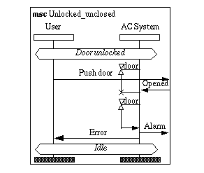
. This may mean that he is blocking the door and this violates access security. This will be considered an error in the system and an error message will be issued. This may mean that an alarm goes and the identity of the violator is logged.
Obviously there are an infinite number of impossible cases . Sometimes it is easier to describe the negation rather than the positive case. This is often the case in legislation. The impossible cases that we choose to specify should serve one of two purposes. Either their nonexistence is important to verify or they will guide the design of the system. In Figure 16 we want to express that it should be impossible to send two Code messages from the User to the System before the User has consumed a Card out message
Figure 16: Impossible case
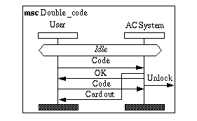
The implementation guidance of this requirement can be that the system will use a card reader which keeps the card until it is explicitly released.
Critical for the success of our system is that nobody should be able to go through the door without having entered an accepted code. Thus we would specify this as a critical impossible case .
Step 1b: Establish the interplay with non-developers
The system interface mscs are often suitable as documentary as well as requirements specifications. The customer will be interested in the end users' situation and on how the system is supposed to act with its surroundings. The project team is interested to validate their views with those of the customer. The managers on both sides want to be assured that the project is on the tracks.
The non-developers want to be informed and they want to be able to influence the development, but they may not be prepared to take joint responsibility for the system. Therefore the project team should be careful to demand that agreement or disagreement should be recorded. The later position that the descriptions could not be understood should be eliminated by involving the non-developers in producing additional mscs.
The non-developers easily get a strong sense for detail when they find themselves being made responsible. Partly this is a deferring strategy and partly it is because they feel that the situations described are not concrete enough for them. In our example the end user representatives could argue that the user interface is not properly detailed as it says nothing about how the Code message is entered. Messages as arrows may actually prove to be too abstract, they need to see the actual hardware. Such illustrations may then be associated with the corresponding MSC messages.
When the non-developers understand that they can handle MSC, they should be encouraged to take part in design as well as requirements specification. They will then be able to see that the requirement side of the model checking is appropriate and will more easily accept the SDL design as the automatic verification ascertains the consistency with the mscs.
We summarize our advice for the interplay with non-developers:
- Require responsibility and approval from the non-developers;
- Involve the non-developers in making additional mscs making sure that they understand MSC and that they understand that they understand MSC;
- Associate concrete input/output with the user interface.
- Encourage the non-developers to use their MSC knowledge during the design and model checking phases
Step 2a: Coping with variants and similarity
When the set of mscs grows, similarities will become increasingly more evident. The need for organizing the maintenance also becomes increasingly urgent.
MSC 92 has few mechanisms to express similarity and variants. We expect that the major difference in MSC 96 compared with MSC 92 will be the ability to cope better with similarities and MSC structure.
In MSC 92 the concept condition is what we shall use. It was introduced in "MSC document and Conditions" where we showed that conditions are not like a predicate, but rather like a label or state. The conditions which are shared by all instances are called global conditions. The global conditions form a set of system "states". The problem with this association is that the condition is not a synchronization mechanism meaning that the instances are not necessarily all "in the same global condition". The conditions are non-existing at execution time. They represent possible connection points at description time.
Still a good strategy during design is to associate MSC conditions with system states of the design system (SDL system). To aid the maintenance of the MSC documents The SDL Methodology Guidelines from 1993 [102] suggests what is later labelled road maps . Mscs and conditions are placed in a directed graph.
Figure 17: Road map
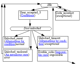
It is quite obvious from Figure 17 that road maps are illustrative only when there is a moderate number of mscs associated with each condition. For larger MSC documents a table may be more appropriate for maintenance purposes.
We recommend using only global conditions to keep the connection graph simple, but MSC 92 also define local conditions which cover only a subset of the instances.
Step 2b: Approach the details
So far we have literally only scratched the surface. Neither the requirements specification nor the design specification will suffice with seeing the system as one instance. Furthermore our first attempts to define messages are most certainly very crude. Any modern communication requires some kind of protocol where messages are passed back and forth to make sure that the information has come properly across. Thus we need to look into more detail the instances and the messages.
The instance hierarchy
MSC has submsc which is meant to describe the communication within an instance. Figure "Decomposed" , Figure "Submsc" and Figure "Instance dynamics" form such a submsc instance hierarchy. As mentioned in "Coregion and submessage charts" the problem with the submsc concept is that the submsc must match the strict ordering of the timeline of the decomposed instance. This is often a much too severe requirement.
There are two practical approaches to this problem.
- Relax the syntax requirement such that the ordering of the decomposed timeline is contained in the set of traces of the submsc. Hope that your tool does not object.
- Rewrite all the mscs which should have decomposed instances such that the submsc substitutes the decomposed instance.
Neither of the two approaches are fully satisfactory. The first approach violates the language definition and the latter does not use the obvious language mechanism. The latter approach also has the disadvantage that either there will be considerably more manual consistency checking during maintenance or most of the top level mscs will become historical. Diagram space may also be scarce as the diagrams will contain an abundance of instances.
Our advice is to follow the first approach if your tool gives the desired results. MSC 96 will most probably resolve the nuisance of the submsc concept.
The message hierarchy
We mentioned in "Step 1b: Establish the interplay with non-developers" that the message Code from the User to the system is too crude. If we think more detailed about an Access Control System we find that Code consists of first entering a Card , then typing a series of digits on a keyboard (the Personal Identification Number ). During this input there may be response from a Display .
MSC has no refinement on messages. Therefore the only legal approach is to rewrite the mscs which include the message type to be refined, substituting with the refinement protocol. This approach has the same deficiency as described in "The instance hierarchy" .
Again it is possible to add some proprietary semantics (and notation) to MSC. Include the message refinement as an msc with a name derived from the message name. Produce a table which associates messages with their refinements. The current tools will hardly handle this properly. It depends on your verification targets whether this approach is at all feasible. If model checking against SDL is the target, it depends whether the SDL system recognize the high level message. Even though the concepts corresponding to the high level messages are present in the SDL design as procedures or services, this presence are not exploited by the tools. To exploit such high level concepts needs information additional to the standard languages. Nevertheless to keep the abstraction levels of your initial analysis present in the SDL design is still highly recommended.
Let us return to our example where we want to refine the Code message from the User to the AC System .
Figure 18: Refinement of Code message

We notice that Figure 18 use instances of a submsc of Panel , and this is typical for refinement that increasing the granularity of the messages will increase the granularity of the instances.
Summary of granularity problems
The transition from lower to higher granularity is a difficult one. Firstly the MSC language is only partly suited to support hierarchical system description. Secondly even for languages which support hierarchical description it is not obvious how these hierarchies should be exploited during the hierarchical system development. MSC has submsc to refine the instances, but no means to refine messages.
The suggestions for object oriented MSC includes a type/object concept which together with a shorthand (msc with a direction) should make the transition from lower to higher granularity easier (Haugen 1994c).
We have in this section "Step 2b: Approach the details" suggested some private notation which, according to our opinion, improves the descriptive powers. On the other hand these private notations are probably not supported properly by the tools. The only safe strategy if the mscs are going to be used formally for verification is to perform substitution of refined concepts into the diagrams of lower granularity. The new diagrams become more detailed, but the old diagrams probably had more documentary power towards certain peripheral groups. The company (project) must decide whether both versions are going to be maintained.
It should also be mentioned that the structuring of the MSC document need not in any way coincide with the structure hierarchies of the corresponding SDL design even though it is reasonable to assume that the hierarchies of instances coincide with SDL block structure.
Step 2c:Express the inexpressible
There are aspects of the behavior of systems which MSC 92 cannot describe. We have already seen in "Step 2b: Approach the details" that MSC 92 has problems describing behavioral structures. In this section we shall go into some areas where MSC 92 does not quite fulfill the needs, but which the users find absolutely necessary to cover.
The idea in this section is that even though MSC cannot express the desired aspects, it is valuable to have some uniform way to express these aspects in comments and to know what their absence means in terms of formal verification.
Causality, dependency, partiality and priority
The concepts causality , dependency , partiality and priority are interlinked as we shall see shortly. First let us repeat that MSC expresses merely that one event comes before another. It does not express that the later event is a result of the earlier. Neither does it express that the former has higher priority than the latter. In fact MSC says nothing about whether there are messages between the instances which are not described. When we express this explicitly it seems reasonable, but when users make their own mscs assumptions about these matters are often made implicitly.
It is quite common to assume that all messages are included. We shall call this message completeness . Message completeness may often be a reasonable assumption, but the converse ( partiality ) is also often the case. Mscs on high abstraction levels should not be crowded with all kinds of synchronizing messages or messages which serve only protocol purposes. Likewise if MSC is used to describe behavior of a windowing system, most of the mouse movement events are removed or else the diagrams will fill up with uninteresting mouse events.
For reactive systems it is reasonable to assume that the output an actor produces in some way is dependent upon the input it receives. It is, however, not evident how this dependency is and how it should be described. If MSC is used to specify a system of SDL 88 processes as instances and if we assume message completeness, we can deduce that the outputs are dependent on the last input. This is because an SDL 88 process is driven entirely by transitions triggered by the consumed input. We may call this (very strict) assumption pure automata instances . It is clear that quite often instances will not act as pure automata and we may feel the need to express causal dependence between an input and a sequence of output on the same instance. Some companies have introduced their own notation for this (See e.g. [86] for proprietary notation at NFT-Ericsson). The MSC standard gives little room for extra graphical notation on the messages. The most reasonable approach is to introduce a naming convention for the names of the messages or a note associated with the message name. This will not change the semantics of the msc and it can be used for verification which is normally not affected by causality.
Figure 19: Expressing dependency

Even when we want to express dependency between an input and an output, it is not such that whenever the given message type is received a message of the dependent type is output. Even when the instances are pure automata this is dependent on the state of the instance. MSC express no state information other than through the conditions, but they have no such semantics.
ITU discusses in this study period an extension of MSC which will make the possibility to express causality relation explicitly (Rudolph 1994). It is probable that such a notation will be included in MSC 96.
In principle priorities may also cause a change of behavior compared with what one would expect without priorities. Either some messages have priority over other messages like interrupts, or some instances have priority over other instances like exception handlers. MSC have no notion of priority as it is not a prescription but a description of some behavior. In MSC where priorities have effect will appear as message overtaking (cf. Figure "Message overtaking" ). What the user wants to express is that this message overtaking is due to priority and not to randomness. This is also most easily achieved by naming conventions.
One should be aware that using priorities not necessarily limits the state space even though it may look that way. Since MSC (and SDL) has no way to express duration of transitions and since external messages may arrive at any time, the situation where priorities affect the outcome is often equal to another situation where priorities had no effect. In that situation the external events were such that messages entered the critical instance in the desired order anyway. Nevertheless in a real world where transitions do take time priorities may improve the implementations. There are of course elaborate priority schemes which do limit the state space like giving priority to internal signals in certain blocks of SDL systems.
In summary we recognize the need to express dependency as a need to express more about why something happens and not only what happens.
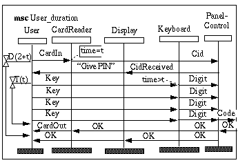
Capacity and Duration constraints
MSC is used for requirements specification. In requirements figures on capacity and response times are often considered of ultimate importance. Therefore it is reasonable to desire that such requirements can be put in the mscs. Even though the desire is reasonable, the achievement is not trivial.
Let us first concentrate on duration constraints . We have the following different cases:
-
within one msc on one instance
The requirement is an expression about the duration between two events on the same timeline. The duration may be either absolute or relative to some other duration. We want to express statements like "The duration from the User inputs the Card until he may enter the access zone should be less than 2 seconds more than the duration of the typing of the PIN ". We may express such requirements in MSC 92 by using timers which are not actually present in the implementation of the system or by attaching comments to the individual events. Such pseudo-timers are shown in Figure "Pseudo-timers to express duration constraints" . The advantages are that the duration becomes very visible and that the duration will be present also in the formal semantics. Disadvantages are that pseudo-timers are not easily distinguishable from real timers and that the timers cannot formally be set and timeout exactly at the same point in time as other events on the same timeline. Conversely the notation with comments associated with events may not convey the sense of duration and they will not exist in the formal semantics.

-
within one msc, but between instances
Duration expression are not always confined to one timeline. Statements like: "The CardReader should register the CardIn before the Keyboard registers the first Key " can only be expressed by comments to the events as shown in Figure "Interinstance duration constraint expressed by comments" . There is some doubt whether it is meaningful to assume a global clock.
-
over the MSC document
Statements like "The User will always get a reply back within 2 seconds after he has typed in the last digit" refers not only to one msc but to the whole MSC document. It assumes that the MSC document contains all relevant mscs. If we use the pseudo-timer notation, we may then define a timer name associated with the requirement which will occur wherever this requirement is expressed.
Capacity constraints are such statements as "The Access Control System should be able to handle 5000 entries per hour". These kinds of requirements can hardly be expressed within the MSC document only. What we may put into the mscs are markers of events which will be counted for capacity measurements. MSC actions may be used. An action is just an informal text in a rectangle on a timeline.
Human Machine Interface
MSC is not targeted to describe aesthetics of the user interface. Neither is MSC particularly suited for describing users' choices since modern user interface is not based on sequences as they were in the old days. Modern user interfaces are based on operations which can be performed almost ad libitum and the setting of their parameters. Parameters may also be set in any order.
To distinguish one user interface strategy from another with MSC seems inadequate. MSC is normally on a higher abstraction level. In our example user interface as you may see in Figure "Interinstance duration constraint expressed by comments" is functionally defined. Nothing is said about the size of the keys of the keyboard, color of the characters of the display or whether the card is a magnetic strip card or a smartcard. From the MSC point of view we could not care less. Nevertheless the user may find these questions most interesting, but other description techniques than MSC should be utilized.
Extensions
There are some basic communication aspects which MSC does not handle.
-
broadcasting/multicast
When one instance outputs equal messages to a set of receivers this cannot be described simply by one message symbol. The only way MSC can describe this is by repeating the broadcast message the appropriate number of times. This appropriate number may not be fixed like the number of subscribers to a telephone conference. In such cases we will include only a very small amount of instances as representatives of the larger set of instances. -
synchronous messages
MSC messages are asynchronous, but synchronous ones are sometimes requested By placing two messages very close together pointing in both directions, a synchronous message can be simulated.
Step 3: Approach the design specification
We assume now that we have reached a situation where we have one or more MSC documents which describe the system. Our next step is to describe the more detailed design. SDL is often used for this purpose, but other languages are also appropriate 6 . The design phase may proceed in two different ways depending on its relation with the existing MSC documents.
- Produce design skeletons from the MSC document;
- Produce design document from scratch and model check against the MSC document.
The first approach assures that the design is consistent with the requirements defined in MSC. This seems intuitively attractive. The possible danger is that the system development becomes too monolithic. There is only one perspective on which the design relies. The second approach on the other hand assures that the design perspective is introduced in addition to the MSC perspective. We mentioned in "What is a message sequence chart?" the difference in perspective between MSC and SDL. The second approach will exploit this difference and consequently a better understanding of the problem domain will be achieved.
The two approaches are principally different, but in practice a concrete development might use a combined approach. If there is a tool which produces SDL from MSC 7 , still the skeletons must be filled in properly. Some inconsistencies will be discovered, but other inconsistencies may be introduced in the design phase. Therefore a subsequent model checking activity is still needed. On the other hand if the development does not use any automatic transition from MSC to SDL, the developers may still take advantage of the understanding achieved through the requirement specification. Their competence and experience with model checking may lead them to produce SDL which is well suited for the subsequent phase.
Aligning SDL and MSC
When we have an MSC document and a supposedly corresponding SDL system it is necessary to align the two descriptions. By aligning we mean to make explicit how the two descriptions correspond. Which message corresponds to which signal? Which SDL block corresponds to which MSC instance? Our advice is to let the names coincide and make this part of the mapping simple.
Both MSC and SDL may describe non-terminating systems. SDL has initial transitions to define the starting state, while MSC documents not necessarily have any explicit start at all. Since the MSC document is normally not complete, we must specify corresponding execution points between the mscs and the SDL system.
We recommend that in defining this execution correspondence the developer should map SDL system states 8 into MSC conditions. The developer must be aware that MSC conditions do not imply synchronization as mentioned in "MSC document and Conditions" . Therefore it may be necessary and advisory to add state invariants as comments in both the MSC and SDL descriptions.
We present here part of the mapping between the example MSC document and the corresponding SDL system which is found in [25] .
|
(idle,idle,locked) 9 |
||||
From Table 3 we see that model checking face more initial problems. Firstly there is the partiality problem. The MSC document may not describe all the messages which the SDL system finds adequate to introduce as signals or the opposite way around. In our example the Push Door message has no counterpart in the SDL description.
Secondly the SDL system and the MSC system may not agree on what objects are in the environment. In our example the MSC document describes the User as an instance while the SDL system defines the user in the environment. Conversely the SDL system defines the Door as a block while it is considered in the environment by the MSC document.
To overcome these discrepancies it is necessary to perform some alignment modifications . Some of the alignment modifications will be a permanent change to the specifications while others are only modifications which are necessary for the model checking to perform. In our example the message name Card Out could be substituted with Eject Card . This could be made permanent 10 . The PushDoor message could be eliminated temporarily so that its existence will not confuse the model checking.
The temporary modifications are often what we call reductions . A reduction is a simplification which has no effect on the result of the verification. Said differently the simplification should be truthful to the original with respect to the purpose of the verification. Reductions may either be mandatory in order to make the model checking work at all or they may reduce the amount of resources needed to perform the check. We may reduce either the SDL description or the MSC description or both to achieve the most practical correspondence.
Reductions may be statical or dynamical. Statical reductions are changes in the descriptions which are based on the static semantics of the description. Such reductions are e.g. elimination of messages and transitions which communicate with instances which are not in the picture for the verification. See [114] . Dynamical reductions take into account the actual execution of the system. Truthfulness can be achieved more accurately, but the effort needed in the reduction is comparable to performing a reachability analysis. See [163] .
There are not adequate tools available to aid in this alignment phase. Therefore manual walkthrough will be necessary to ascertain the consistency of the simplifications. It is especially critical that the statements of truthfulness is made explicit and checked with scrutiny. See [85] for more general information on walkthroughs.
Impossible and possible mscs
We have classified the individual mscs in the MSC document according to validation predicate categories in Table "MSC document table" . Our first effort in model checking will be to check existence. Existence is quite simple to check manually as well as automatically. Firstly the msc and the SDL system is aligned according to the alignment information. At each point in time the msc defines a finite set of events which are possible next events. Likewise the SDL system defines a finite set of events which are possible after all transitions internal to blocks which are one instance in the msc are executed. If the MSC set of events is a subset of the SDL set of events, the msc is still perfectly possible , and we go on from the states given by the set of MSC events until we reach all ends of instance. If the MSC set of events is not a subset of the SDL set of events, but their intersection is non-empty, the msc is sometimes possible which means there are sequences described by the msc which cannot happen in the SDL system. If the intersection set is empty the msc is impossible .
Then we compare the verdict of the existence comparison with the category in the MSC document table. Impossible mscs should have been categorized impossible. Mscs of other categories should be perfectly possible. Mscs which are sometimes possible should indicate that either the SDL or the MSC descriptions are slightly wrong. Most often there are only small modifications needed.
Complete subtree
Sometimes checking for existence is not considered sufficient. The designer wants to express that he has described the complete set of situations from a given starting state. In our example we may state that "All that can happen to the user after he has entered his card is that he gets OK or NOK to enter, and he gets his card back".
The execution sketched in "Impossible and possible mscs" results in a tree structure of possible executions. This tree is just like the tree described by the formal definition of MSC. We call such trees asynchronous communication trees . Our checking for complete subtree means that the tree induced by a given MSC document (or part of one) is identical to the tree induced by the SDL specification, but which is pruned properly. We may ignore all branches which go beyond where the MSC tree has terminated.
Figure 22: Checking for complete subtree
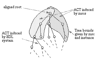
The requirement is that the MSC document shall induce a tree which either includes all successor nodes of a given node in the SDL tree or none of the successors. The problem may become quite complex since the SDL tree may be infinite. The MSC tree may also become infinite if we accept the interpretation that conditions give implicit combinations which may result in loops (cf. "MSC document and Conditions" ). It is reasonable to believe that such analysis involves too much book-keeping to be performed manually. The minimum tool support should be an SDL simulator preferably driven by MSC.
Manual model checking
The state space exploration techniques explained in "Impossible and possible mscs" and "Complete subtree" are not sufficient to check the duration constraints and capacity requirements mentioned in "Capacity and Duration constraints" . Tools may eventually provide user-supplied duration information associated with each transition such that a simulation would also include simulation of the time it takes. This may then be compared with the requirements.
For the time being the most practical way is to try and find the worst case through simulation and then do calculations on that manually.
Step 4: Produce test mscs
We refer the reader to the theses of Jens Grabowski [68] and Robert Nahm [140] for a more thorough treatment of the matter. In this section we shall give a few hints to what aspects of the earlier development work is important in this phase and requirements for the test mscs.
Isolating the IUT
Firstly it is necessary to find the most useful places to put the test probes and test stimulants. We want to harvest as much information as possible from a test. Therefore the interesting events should not be hidden to the test probes. On the other hand we may not necessarily want to input a very long detailed sequence of messages. Thus in isolating the "implementation under test" (IUT) we try to observe all interesting results with the least input effort.
On the other hand the probes cannot be placed on instances which are not known to the mscs we want to test. The requirements mscs will often have more high level instances.
Projecting the already existing mscs
Seen from the point of the requirements mscs, the test probes (and test stimulants) are instances or set of instances. To get a test msc from a requirements msc, we must project the requirements msc onto the instances of the test probes and stimulants. This can in principle be done automatically.
Also documentary and design mscs may serve as bases for test mscs.
Finding new test mscs
The new test mscs should highlight the intricacies of the concrete design and the implementation. Areas of considerable concurrency should be covered concienciously.
Figure 23: Summary of methodology
