|
Tutorial on SDL-88 Belina, Hogrefe (edits Reed) |

|
|
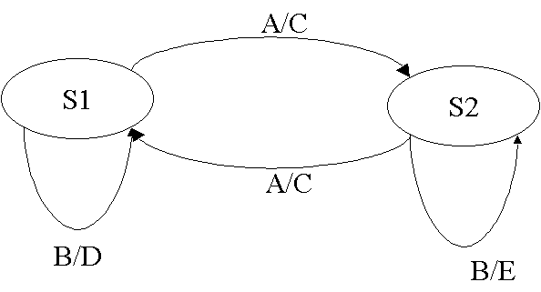
A process in SDL is an extended finite state machine, that is a finite state machine that can use and manipulate data stored in variables local to the machine. The way a finite state machine behaves is described by states and transitions. Figure 8 shows a finite state machine defined by a directed graph.
Figure 8: A finite state machine as a
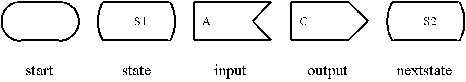
directed graph. Two states S1 and S2 are involved. If the machine is in State S1, it can perform a transition to state S2, initiated by an input A (the consumption of signal A). During the transition it produces an output C (that is, sending of signal C). The input B in state S1 results a transition to the same state with an output of D, and so on. In SDL-88 there are five basic constructs for the describing the state machine of a process: start, input, output and nextstate. Figure 9 shows the SDL/PR representation of these constructs. When the state machine is created, action begins at the transition that follows the start symbol.
Figure 9: Basic constructs for the state
machine of a
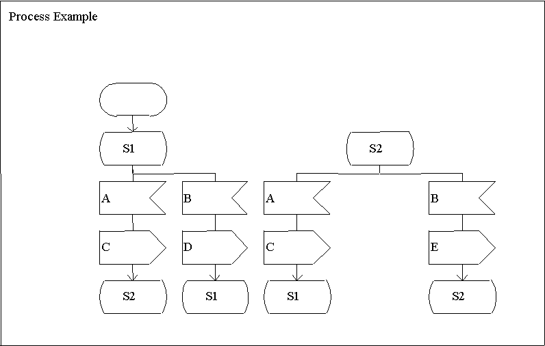
process Figure 10 shows the definition of the finite state machine of figure 8 by a process diagram. The figure shows syntactically correct SDL-88. The frame around the process diagram is optional, if it corresponds to a physical boundary (such as a page in document); otherwise, the frame is necessary to uniquely delimit the diagram. In general it is advised to include the frame even if it is not needed.
Figure 10: Definition of the finite state machine of figure 8 by a process diagram
|
|
Contact the webmaster with
questions or comments about this web site. |